PCB Prototype 1 Manufacturing: Problems and Solutions
Prototype 1:
Here is our first prototype! Originally, the battery holders were at 0 degrees, but as Paul mentioned during our Design Review, since the yo-yo will be rotating at high speeds, it would be a better design decision to angle them (at around 45 degrees) so the batteries won't fly out when the board is spinning.


Batteries Angled at 30 Degrees
Manufacturing the PCB:
The printed circuit board was sent to an external manufacturer. In order to do this, we created gerber files of the Citgo yo-yo PCB in Autodesk Eagle and identified a PCB thickness of 0.06in.
The CAM outputs and Gerber files can be found in this folder:
https://drive.google.com/drive/folders/1JQtPyZCC6OHeAK4E-iSHF6l4740hdE65?usp=sharing

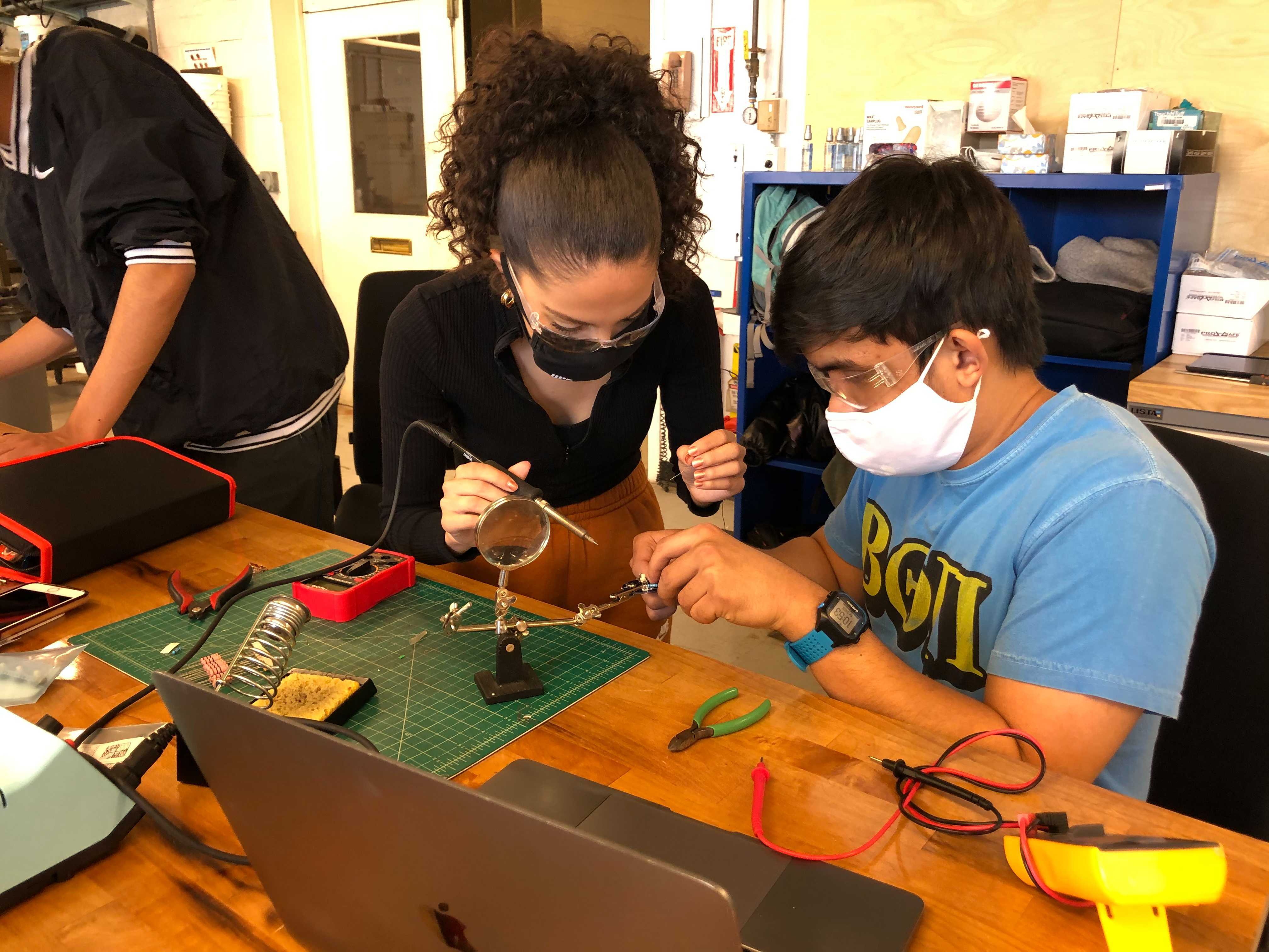
Soldering Board:
Board Problems and Possible Solutions:
The first prototype of a printed circuit board is currently assembled, however when the push-button switch is pressed, the two LEDs on the board do not light up. We examined all the possible reasons why this may be occurring:
- There are two 3V batteries in series to light up the LEDs, for a total voltage of 6Vs. Each LED in this circuit has a lead voltage of 2.9V. Since the two LEDs are in series, we need a total of 5.8 V to light up the LEDs. We checked the voltages of both batteries with a multimeter on the PCB and each battery measured to 3.10V. This removes the issue of a) not enough lead voltage to power the yo-yo and b) the effectiveness of the soldered joints of the battery surface mount containers.
- The diodes may be placed in the incorrect direction. The anode (short end of the LED) and cathode (long end of the LED) may need to switch for either or both of the LEDs.
- The resistor value may be incorrect. Currently, the value is R = 10 Ohms. However, when using a multimeter to check the current on the traces, we measured 0.2 Amps. The LEDs need a current of 20 mA to function.
- R = 0.2V/0.02A = 10 Ohm
- The mechanics and circuitry within the push-button switch may not reflect how we assume it is performing. Also, the proximity of the surface mount battery holders to the button may be affecting its performance by short-circuiting the circuit since the two parts occasionally touch on the small PCB.
Since the push-button switch is a black box within our circuit, we will use jumper wires on a bread-board to make sure all other parts of our PCB are working as planned (possible reasons #1-3 above). If our circuit works without the button (our LEDs light up), the next step will be to fully understand how our selected push-button switch works and modify our circuit accordingly (possible reason #4 above).
Here is Rima working on the PCB to make sure the traces on the PCB match the correct circuit wiring:

Ultimately, the problem was the push button switch was wired incorrectly in our design.
To solve, we used an exacto knife to cut the traces on the board so only the correct terminals on our button were connected to the circuit. Once all the incorrect traces were cut, our PCB final works! Yay!
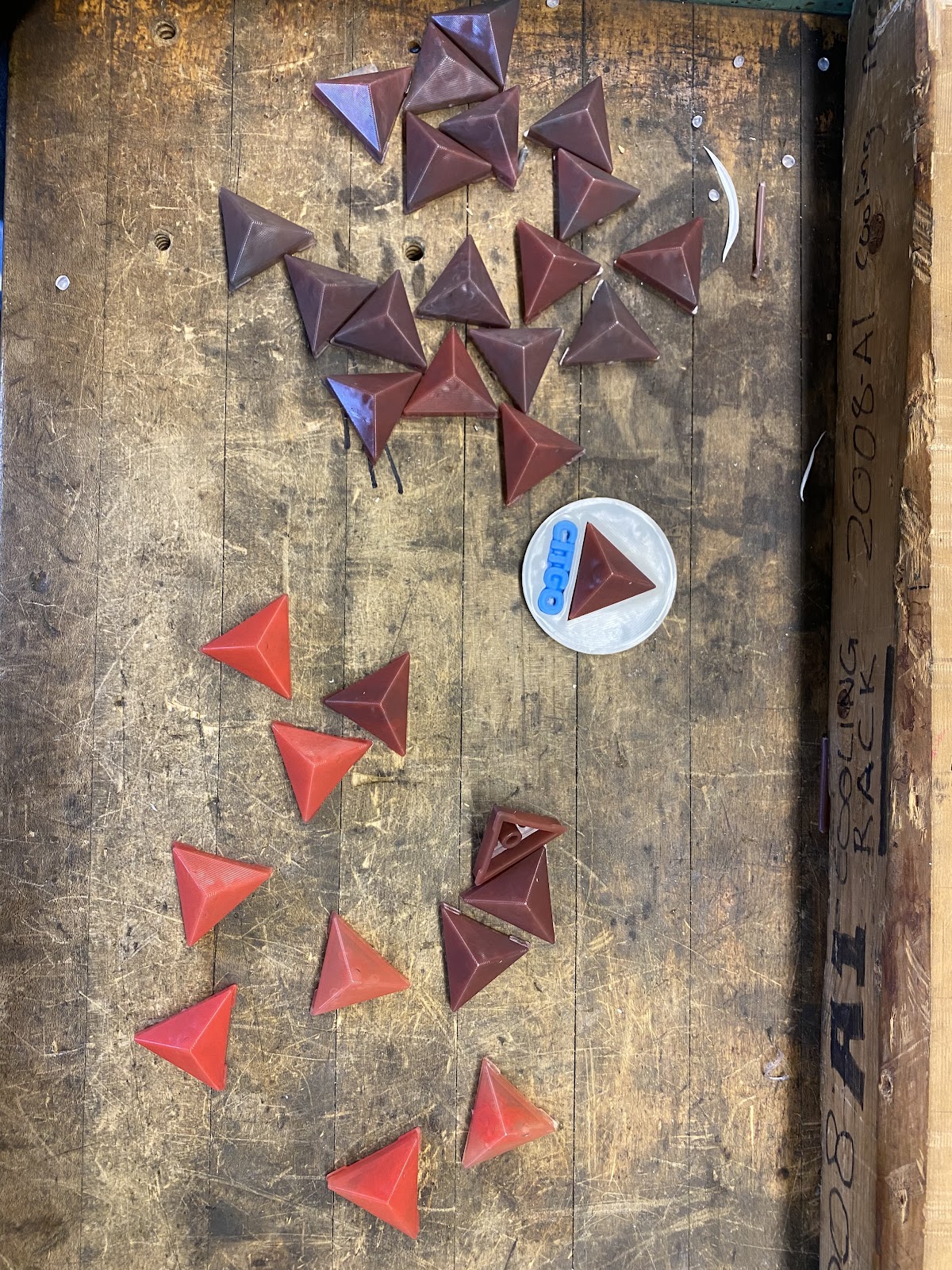
Here is our working PCB within our 3D printed yo-yo prototype:D


Comments
Post a Comment