Final PCB Designing and Fusion 360 Integration
Creating Custom Footplates in EAGLE:
The push button switch we chose had a unique footplate that we had to create in order for the switch to be placed properly on the board. Looking at the data sheet of the button, we were able to find the dimensions of all of the pads and through holes within the footplate and create a new part within our EAGLE library.

Here is a screenshot of the library editor, where we replicated the correct footplate for the button:

Creating Custom 3D Packages in EAGLE:
As mentioned in and earlier, we had to create custom 3D packages for all of our parts in order to be properly exported into our Fusion 360 folder. For the push button switch and coin cell retainers, we were able to find CAD files of the parts. For these, we just needed to upload the .STL files and properly place them on the pads.


For the resistor and LEDs, we had to create a an extrusion with the same dimensions as our parts to make sure our PCB and the electronic dimensions fit together with the rest of our mechanical design, since a problem that we had with our first iteration was that our LEDs were to tall and hitting the base of the triangle piece when the button was pushed.

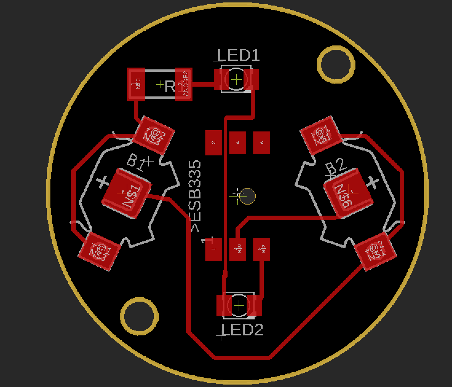
Final PCB Design:
Here is our final PCB design, with our new surface mounted LEDs and resistors, as well as a new hole placement for our screws to screw into the body, since the previous hole placements for the screws interfered with the placement of the coin cell battery.

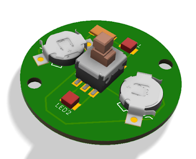
Final PCB in Fusion 360:
Because of the custom 3D packages we made in EAGLE, the export of the PCB from EAGLE to Fusion 360 was seamless.


Comments
Post a Comment